
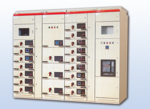
In the MNS system, after components are assembled, a simple mechanical and electrical functional component can be formed. The power and control components are withdrawable.
The total height of functional unit compartments is 72E.
In the same switch cabinet, the drawer units can be assembled singly or mixedly in one cabinet. The general arrangement rule is that small functional units are at the top and large functional units are at the bottom. The maximum number of drawers a cabinet can accommodate in a single assembly is shown in the table below:
| Drawer type | 8E/4 | 8E/2 | 8E | 16E | 24E |
| Maximum number of units | 36 | 18 | 9 | 4 | 3 |
In withdrawable switch cabinets or cabinets with mixed withdrawable and fixed switches, branch busbars (right-angle L-type
Segments 50x30x 5[mm]) are installed in multifunctional dividers made of insulating material. Starting from the same busbar, the protection level against electric shock (IP20) can be achieved without adding partitions. The multifunctional partition board has the performance of isolating fault arc and serves as the isolation between the device compartment and the busbar compartment.
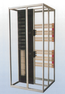
(L-shaped) branch busbar branch busbar in multi-functional partition board
Switch handle position description
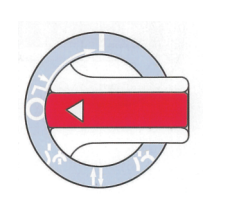
Working position – main switch closed, drawer locked. The main switch is opened – the main circuit is disconnected, the control circuit is disconnected, and the drawer is locked. Test position – the main switch is open, the control circuit is connected, and the drawer is locked. Withdrawal position – both main circuit and control circuit are disconnected. Isolation position – withdraw 30mm distance, the main circuit and control circuit are disconnected, and the drawer is locked. Only after pressing the operating handle inwards can it turn from the ○ position to the ○ position. Padlocks can be added to the main switch opening, testing and isolation positions on the operating handle. As a safety protection, up to 3 locks can be added.
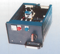
8E, 16E and 24E drawers
The drawer structure of 8E to 16E includes an instrument panel and a back cover made of insulating material, a front cover, metal side panels and wire troughs.
The drawer has two specifications: the drawer has a test position without being drawn out or the drawer has a test position after being drawn out.
The hinged drawer door makes it easy to replace components (such as fuse replacement) without having to pull out the drawer.
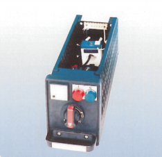
The drawer unit that “has a test position without being drawn out” must be opened with tools before it can be opened in the working position or test position. The front door can be opened by hand when the drawer is in the isolation position.
The drawer unit has a “test position” after the drawer is pulled out. The front door can be opened by hand in the test and isolation position.
Cutouts in the front doors are used for the arrangement of the instrument panel. The position of the instrument panel remains in place when the front door is opened or closed. The instrument panel has knock-out holes for installing metering operations and indicating devices.
The operating handle has electrical (2 open and 2 closed micro switches) and mechanical interlocking functions.
The main switch operation is provided with a separate handle. And it has mechanical interlocking with the operating handle of the drawer test position.
The switch handle can be locked in the working position. The test and isolation positions can also be locked with up to 3 padlocks