
Use
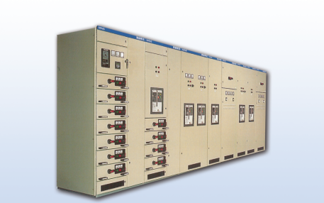
Product Features Conditions of Use MNS low-voltage withdrawable switch cabinet (referred to as switch cabinet) consists of two parts: power center cabinet (PC) and motor control center cabinet (MCC). Suitable for AC 50-60Hz, rated working voltage 660V and below control power distribution system. It is used for power users such as power plants, substations, industrial and mining enterprises, etc., as the power conversion and distribution control for power distribution, motor control, lighting and other power distribution equipment. In addition to general land use, this switch cabinet can also be used in offshore oil drilling platforms and nuclear power plants after special treatment. This switch cabinet complies with IEC60439, VCE0660
Part 500 and GB7251-05 “Low-voltage complete switchgear” national standard, JB/T9661-1999 “Low-voltage withdrawable switchgear complete set” industry standard.
Features
★Compact structure can accommodate more functional units in a smaller space, saving user investment.
★The cabinets can be arranged back to back, and the same cabinet can be freely combined into two types: fixed and withdrawable.
★The structure is highly versatile and flexible in assembly. Corresponding protection levels can be designed according to different requirements of work and environment.
★All standard modules are used, and the series is standardized, making it easy for engineering designers to choose.
★Uniquely designed mechanical locking mechanism, flexible and convenient to operate, no special complicated tools required.
★A large number of high-strength flame-retardant engineering plastic components are used to ensure the personal safety of operators.
★According to the different cable outlet methods, you can choose two options: side outlet or rear outlet.
★High technical performance, the main parameters have reached the contemporary international technical level.
Conditions of Use
★Atmospheric conditions: The air is clean, and the relative humidity does not exceed 50% at the maximum temperature of +40°C. Higher relative humidity is allowed at lower temperatures, such as 90% at +20%. It should be taken into account that humidity condensation may occasionally occur due to temperature changes.
★The altitude does not exceed 2000m.
★This device is suitable for transportation and storage at the following temperatures: -25℃ to +55℃, up to +70℃ in a short period of time (not more than 24h). The device should not be subjected to these extreme temperatures. Any irreversible damage, and it should be able to work normally under normal conditions. If the above conditions of use cannot be met, the user and the manufacturer should negotiate to resolve the issue.
The main technical parameters
| Rated operating frequency (Hz) | 50 60 |
| Rated working voltage (V) | 400 690 |
| Rated insulation voltage (V) | 690 1000 |
| Maximum working current (A) | Horizontal bus 6300 Vertical busbar 1000 |
| Effective value (1s) Peak value (kA) | 60/ 130-150 |
| Enclosure rating | IP30, IP40, IP54 |
| Overall dimensions: height x width x depth | 2200 x 600(800, 1000) x 600(800, 1000) |
Structure
Cabinet structure
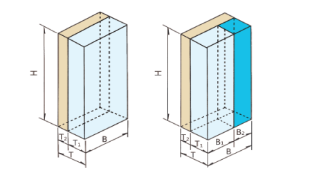
The basic frame of the device is a C-shaped profile combined device structure. C-shaped profiles are bent from copper plates with E=25mm module mounting holes. All structural parts of the frame are galvanized. According to the changes in the primary circuit plan, the necessary doors, sealing plates, partitions, mounting brackets, busbars, functional units and other components are added to assemble a complete switch cabinet. The basic structure of the cabinet is shown in the figure below. The basic dimensions of the cabinet are as shown in the table below.
| H (high) | B(Width) | B1(Width) | B2(Width) | T (deep) | T1(deep) | T2(deep) |
| 2200 | 600 | 1000 | 750 | 250 | ||
| 2200 | 600 | 1000 | 750 | 250 | ||
| 2200 | 800 | 1000 | 750 | 250 | ||
| 2200 | 1000 | 600 | 400 | 1000 | 400 | 200 |
| 2200 | 1000 | 600 | 400 | 1000 | 750 | 250 |
| 2200 | 1000 | 600 | 400 | 1000 | 400 | 600 |
| 2200 | 1000 | 600 | 400 | 1000 | 400 | 200 |
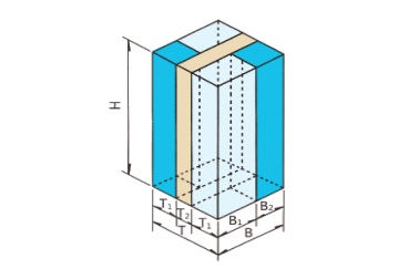
Cabinet partition design
The MCC cabinet can be composed of a single-sided operation cabinet or a double-sided operation cabinet as needed, and each cabinet is fixedly divided into three small compartments. That is, the device compartment, the busbar compartment and the cable compartment, see the figure for details.
Security protection system
Each cabinet is equipped with a flame-retardant high-density polyurethane plastic functional board, which is installed between the main busbar room and the electrical appliance room. Its function is to effectively prevent accidents caused by short circuits between arcing and busbars caused by faults in the switching components. Strict isolation measures were taken. The upper and lower drawers are separated by galvanized metal bottom plates with ventilation holes. The smaller 8E/4 and 8E/2 drawers are surrounded by flame-retardant engineering plastic parts, so there is strong isolation between adjacent circuits. effect.
The cabinet uses a variety of engineering plastic components to support the live parts. These components are required to be halogen-free and have CTI300 anti-leakage performance.
Protective and neutral connection strips
The MNS system can be configured as a 4-wire or 5-wire busbar system.
The protection/neutral line strip is installed horizontally under the device compartment and cable compartment, and is fixed with insulators. The length of the row is determined by the transport unit division.
The protection/neutral wire connection bar is installed vertically in the cable compartment and fixed with insulators, and the length is the same as the height of the cabinet.
There are modular holes on the PE, N and PEN rows and connection rows for cable connection.
The protection line can be directly connected to the fixed drawer with a section of 35mm2.